How to draw a 19-inch rack diagram
A good rack diagram lets anyone on site find a port in seconds. This guide covers rack sizes, a proven device layout, labelling and the port map — the same structure RACK-LIVE-DIAGRAM draws for you.
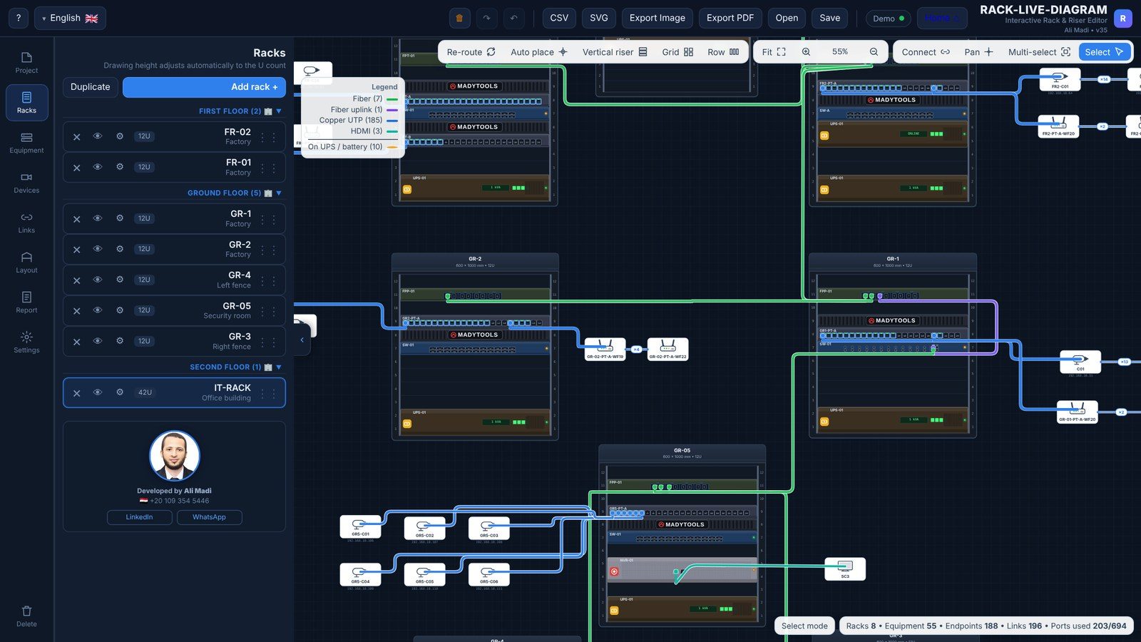
Rack basics
- 19-inch is the mounting width of the equipment (482.6 mm including the ears).
- 1U = 44.45 mm (1.75″) of height. A 42U rack is about 2 m tall; wall cabinets are commonly 6U–15U.
- Common floor-rack sizes: 600 × 600, 600 × 800, 800 × 800 and 800 × 1000 mm (width × depth). Use 800 mm width when you need vertical cable managers, and 1000 mm depth for servers.
A proven layout (top to bottom)
- Fiber ODF / patch panel for the backbone links.
- Copper patch panels, each followed by a 1U horizontal cable manager.
- Access switches facing their patch panels (short patch cords, 0.5–1 m).
- Core / aggregation switch, router or firewall.
- NVR, servers and storage (heavier equipment lower).
- UPS and batteries at the bottom; PDUs at the rear or on the sides.
Leave 10–20 % free U for future expansion and keep blanking panels in empty spaces to control air flow.
Labelling
Follow a simple, consistent scheme inspired by ANSI/TIA-606: floor – rack – panel – port, for example GF-R01-PP02-17. Put the same ID on both ends of every cable, on the patch-panel port and on the outlet in the field.
The port map
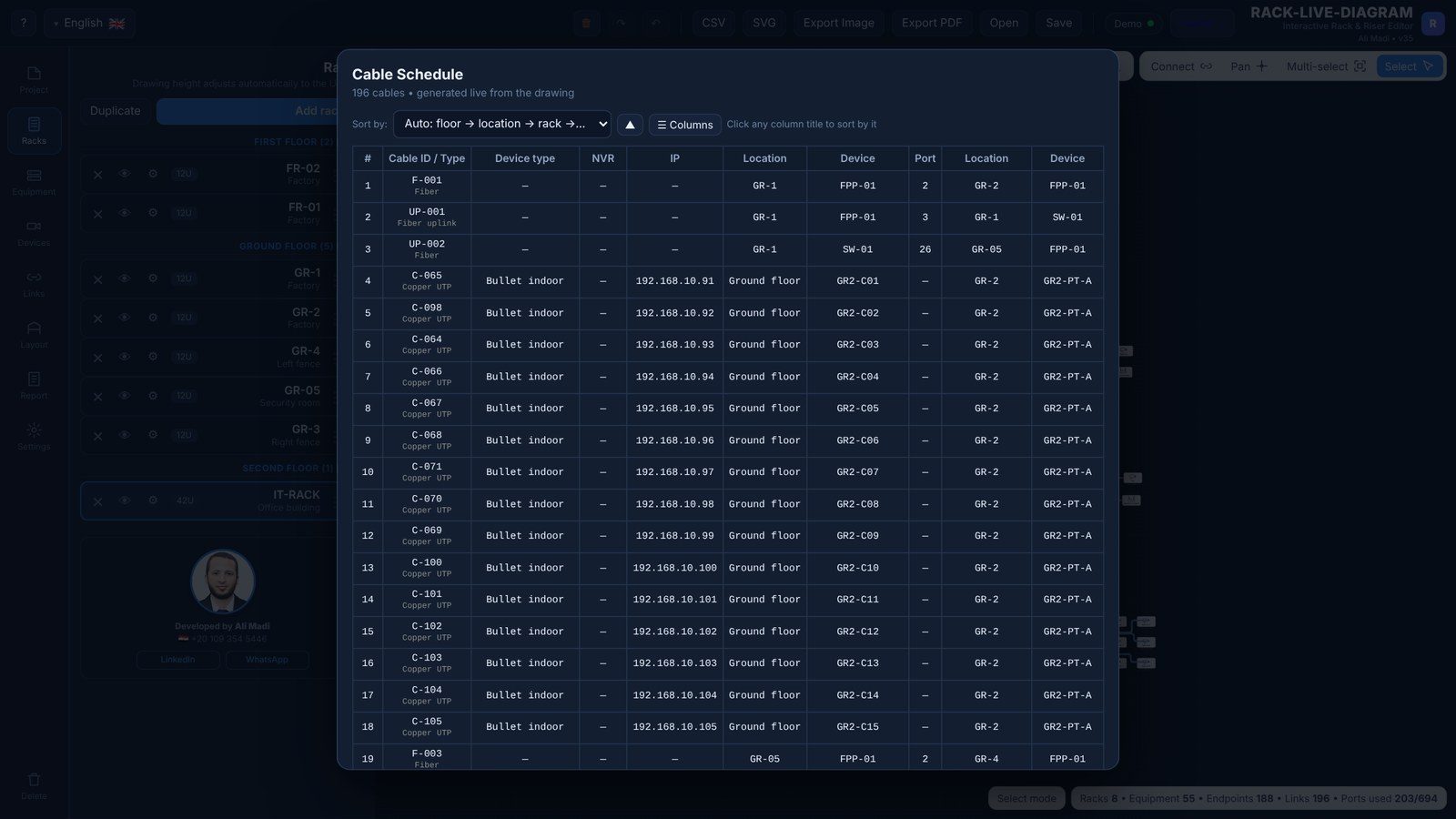
The port map is the table that connects everything: cable ID, from device and port, to device and port, cable type, cores and length, location and IP address of the field device. Sort it by floor and location so the site team can work room by room.
Riser diagram
For multi-floor buildings, draw a riser: one rack per floor (or per telecom room) and the backbone between them — fiber cores or copper — with the main distribution rack at the bottom or in the data room.
RACK-LIVE-DIAGRAM builds the elevation, the riser and the port map from one project, and exports them to PDF and Excel.
Draw network racks the way they are installed on site: 19-inch rack elevations, patch panels, switches, fiber, NVRs and every cable between them — then export a clean cable schedule and port map for the handover file.
Open RACK-LIVE-DIAGRAM →Frequently asked questions
How tall is a 42U rack?
About 2 metres overall: 42 × 44.45 mm = 1.87 m of mounting space plus the frame, roof and plinth.
Should patch panels be above or below switches?
Most installers alternate patch panel and switch, or put each switch directly below its patch panel, so patch cords stay short.
What is the difference between a rack diagram and a riser diagram?
A rack diagram shows the devices inside one rack; a riser diagram shows all racks in the building and the cables between them.
Related guides
How to calculate NVR storage for CCTV cameras
Step-by-step NVR / DVR storage calculation for IP cameras: the bitrate formula, typical bitrates for H.264 and H.265, motion recording, RAID and a free storage calculator.
Read the guide →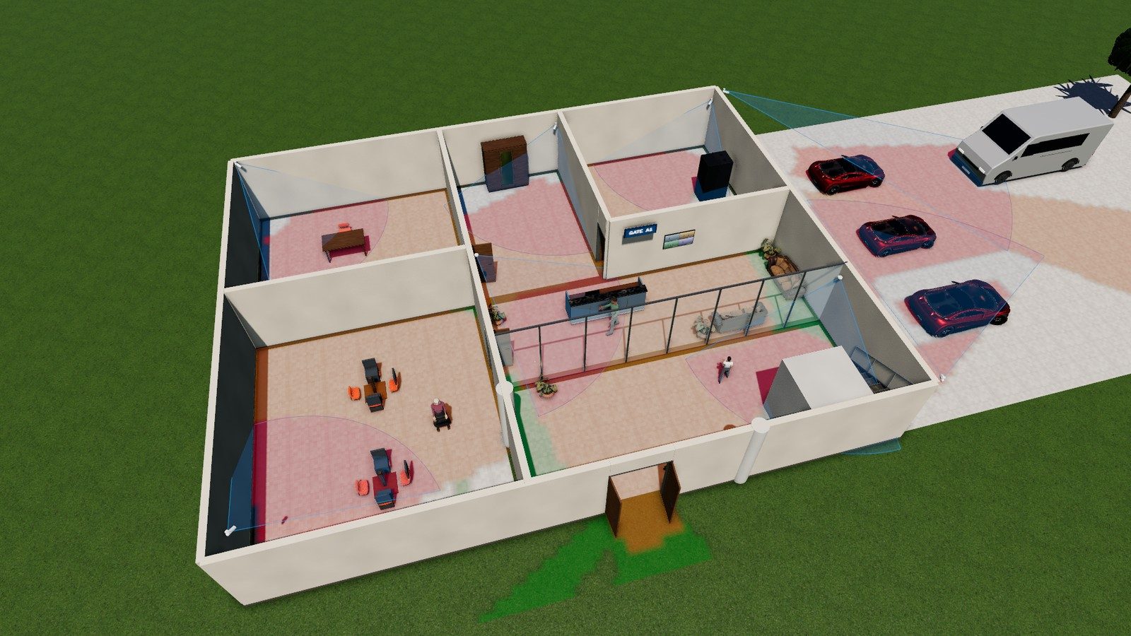
DORI in CCTV: pixel density made simple
What DORI means in CCTV design, the IEC EN 62676-4 pixel-density values (25, 63, 125, 250 px/m), how to calculate pixels per metre at any distance and a free calculator.
Read the guide →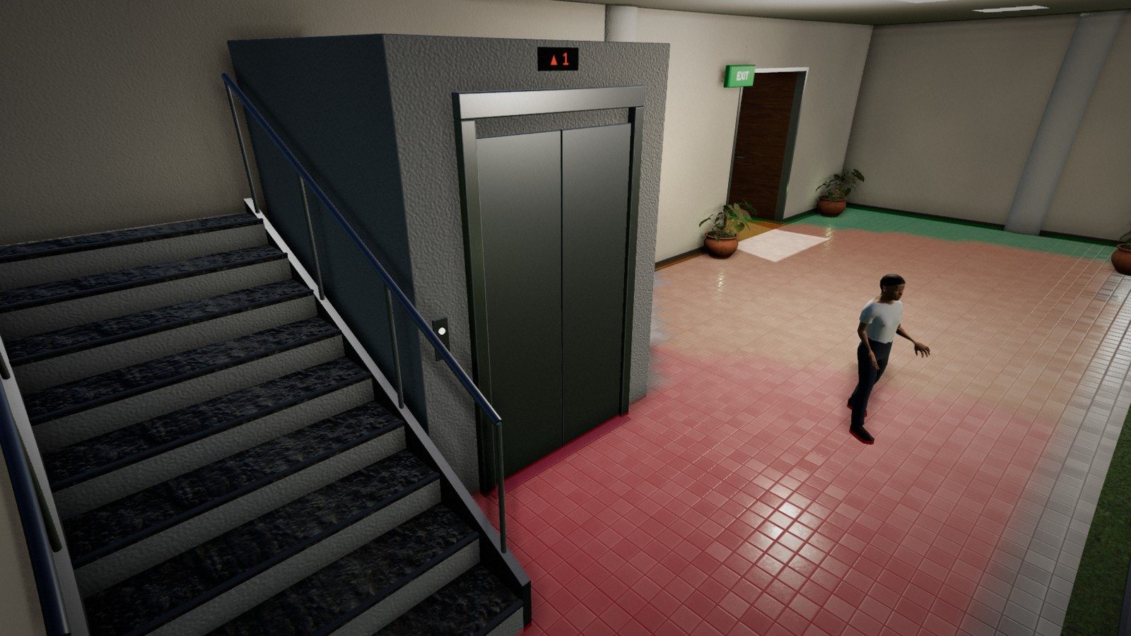
How to choose a CCTV lens (focal length & field of view)
Choose the right CCTV camera lens: 2.8 mm vs 4 mm vs 6 mm vs 12 mm, the focal length formula, field-of-view angles for common sensors, varifocal and motorised lenses, plus a lens calculator.
Read the guide →